Page 33 - ZSi-Foster Channel Loads
P. 33

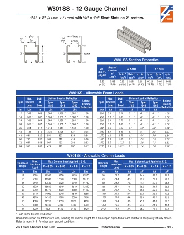
W801SS - 12 Gauge Channel


                      5
                                                        9
                                                                1
                     1 ⁄8" x 2" (41mm x 51mm) with  ⁄16" x 1 ⁄8" Short Slots on 2" centers.


                     5
                    1 ⁄8"                       41mm
                                          10
              3 ⁄8"  7 ⁄8"                mm    22mm


               X             2"            X             51mm
                                                                             W801SS Section Properties
                      Y                           Y
                                                                         Area of
                                                                   Wt..   Section     X-X Axis          Y-Y Axis
                                                                  Lbs./Ft.   in. 2
                                                                  (Kg/M)        lx in. 4   Sx in. 3  rx. in. ly in. 4  Sy in. 3  ry in.
                                                                             2
                                                                          (cm )  (cm )  (cm )  (cm)  (m )  (cm )  (cm)
                                                                                   4
                                                                                                     4
                                                                                                            3
                                                                                         3
                                                                   2 .92  0 .859  0 .261  0 .261  0 .551  0 .325  0 .400  0 .615
                                                                   (4.35)  (5.54)  (10.86)  (4.28)  (1.40)  (13.53)  (6.55)  (1.56)
                                               W801SS - Allowable Beam Loads
                   Max.    Defl.   Uniform Load at Deflection            Max.    Defl.   Uniform Load at Deflection
             Span Uniform   at   Span    Span    Span   Lateral    Span Uniform   at   Span    Span    Span   Lateral
                   Load   Load   /180    /240    /360   Bracing          Load   Load   /180    /240    /360  Bracing
              In   Lbs     In    Lbs     Lbs     Lbs   Reduction   mm     kN    mm      kN      kN     kN    Reduction
              12  1,368 *  0 .00  1,368 *  1,368 *  1,368 *  1 .00  300  6.1 *  0.11  6.1  *  6.1  *  6.1  *   1.00
              18  1,368 *  0 .02  1,368 *  1,368 *  1,368 *  1 .00  450  6.1 *  0.36  6.1  *  6.1  *  6.1  *   1.00
              24  1,368 *  0 .04  1,368 *  1,368 *  1,368 *  1 .00  600  6.1 *  0.86  6.1  *  6.1  *  6.1  *   1.00
              30  1,368 *  0 .07  1,368 *  1,368 *  1,368 *  1 .00  750  6.1 *  1.68  6.1  *  6.1  *  6.1  *   1.00
              36  1,314    0 .12  1,314    1,314    1,143    1 .00  900  5.9    2.83  5.9     5.9     5.2      1.00
              42  1,125    0 .16  1,125    1,125    837    0 .98   1050  5.1    3.86  5.1     5.1     3.8      0.97
              48   981    0 .20  981     963     639     0 .94     1200  4.4    5.03  4.4     4.4     3.0      0.94
              60   783    0 .32  783     612     414     0 .88     1500  3.6    7.88  3.6     2.8     1.9      0.89
              72   657    0 .46  567     423     288     0 .83     1800  3.0    11.32  2.6     2.0     1.3     0.83
              84   558    0 .62  423     315     207     0 .77     2100  2.5    15.31  1.9     1.4     1.0     0.78


                                              W801SS - Allowable Column Loads
                       Max.      Max. Column Load Applied at C.G.            Max.      Max. Column Load Applied at C.G.
             Unbraced  Slot Face                                  Unbraced  Slot Face
              Height          K = 0.65  K = 0.80  K = 1.0  K = 1.2  Height          K = 0.65  K = 0.80  K = 1.0  K = 1.2
                       Load                                                  Load
               In      Lbs      Lbs     Lbs      Lbs     Lbs        mm        kN      kN      kN       kN      kN
               12      5660    19300   18950    18430   17870        300     25.2     85.9    84.4    82.2     79.7
               18      5560    18500   17870    17000   16160        450     24.8     82.5    79.7    75.9     72.2
               24      5440    17580   16720    15640   14720        600     24.2     78.5    74.7    69.9     65.8
               30      5320    16650   15640    14510   13590        750     23.7     74.4    69.9    64.9     60.9
               36      5210    15770   14720    13590   11460        900     23.2     70.5    65.8    60.9     51.9
               42      5110    14990   13940    11810    9360       1050     22.8     67.0    62.4    53.4     42.6
               48      4920    14310   12880    10050    7400       1200     22.0     64.0    58.1    45.7     33.9
               60      4320    12710   10050    6820     4730       1500     19.4     57.3    45.7    31.3     21.8
               72      3660    10400    7400    4730     3290       1800     16.5     47.2    33.9    21.8     15.1
               84      3030    8200     5430    3480     2420       2100     13.8     37.5    25.0    16.0     11.1
            * Load limited by spot weld shear
            Beam loads shown are total uniform load, including the channel weight, for a simple span supported at each end that is adequately laterally braced.
            Refer to pages 3 - 6  for other beam support conditions.
            ZSi-Foster Channel Load Data                            zsi-foster.com                             – 33 –
   28   29   30   31   32   33   34   35   36   37   38