Page 38 - ZSi-Foster Channel Loads
P. 38

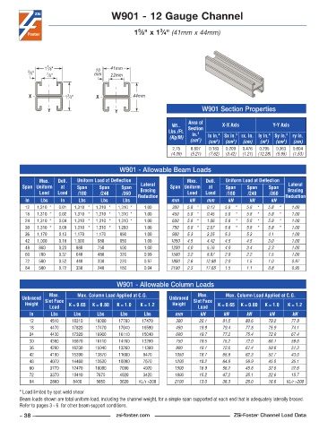
W901 - 12 Gauge Channel


                                                           3
                                                   5
                                                  1 ⁄8" x 1 ⁄4" (41mm x 44mm)


                  5
                 1 ⁄8"                   41mm
                                    10
           3 ⁄8"  7 ⁄8"            mm    22mm

            X            1 ⁄4"      X            44mm
                          3
                  Y                        Y                               W901 Section Properties

                                                                      Area of
                                                                Wt..   Section    X-X Axis          Y-Y Axis
                                                              Lbs./Ft.   in. 2
                                                               (Kg/M)        lx in. 4   Sx in. 3  rx. in. ly in. 4  Sy in. 3  ry in.
                                                                         2
                                                                      (cm )  (cm )  (cm )  (cm)  (m )  (cm )  (cm)
                                                                                                  4
                                                                                      3
                                                                                                        3
                                                                                4
                                                                2 .75  0 .807  0 .183  0 .209  0 .476  0 .295  0 .363  0 .604
                                                               (4.09)  (5.21)  (7.62)  (3.42)  (1.21)  (12.28)  (5.95)  (1.53)
                                             W901 - Allowable Beam Loads
               Max.    Defl.   Uniform Load at Deflection            Max.    Defl.   Uniform Load at Deflection
         Span Uniform   at   Span    Span    Span   Lateral    Span Uniform   at   Span    Span    Span   Lateral
               Load   Load   /180    /240    /360   Bracing          Load   Load   /180    /240    /360   Bracing
          In    Lbs    In     Lbs     Lbs     Lbs  Reduction   mm     kN    mm      kN      kN      kN   Reduction
          12   1,310 *  0 .01  1,310 *  1,310 *  1,310 *  1 .00  300  5.8 *  0.13  5.8  *  5.8  *  5.8  *  1.00
          18   1,310 *  0 .02  1,310 *  1,310 *  1,310 *  1 .00  450  5.8 *  0.45  5.8  *  5.8  *  5.8  *  1.00
          24   1,310 *  0 .04  1,310 *  1,310 *  1,310 *  1 .00  600  5.8 *  1.06  5.8  *  5.8  *  5.8  *  1.00
          30   1,310 *  0 .09  1,310 *  1,310 *  1,280    1 .00  750  5.8 *  2.07  5.8  *  5.8  *  5.8  *  1.00
          36   1,170    0 .13  1,170    1,170    890    1 .00   900  5.3    3.25   5.3     5.3     4.1     1.00
          42   1,000    0 .18  1,000    980     650    1 .00   1050  4.5    4.42   4.5     4.5     3.0     1.00
          48   880    0 .23  880     750     500      1 .00    1200  4.0    5.76   4.0     3.4     2.3     1.00
          60   700    0 .37  640     480     320      0 .99    1500  3.2    8.97   2.9     2.2     1.5     1.00
          72   580    0 .52  440     330     220      0 .97    1800  2.6    12.88  2.0     1.5     1.0     0.97
          84   500    0 .72  330     240     160      0 .94    2100  2.3    17.68  1.5     1.1     0.8     0.95


                                            W901 - Allowable Column Loads
                   Max.      Max. Column Load Applied at C.G.            Max.      Max. Column Load Applied at C.G.
         Unbraced  Slot Face                                   Unbraced  Slot Face
          Height          K = 0.65  K = 0.80  K = 1.0  K = 1.2  Height          K = 0.65  K = 0.80  K = 1.0  K = 1.2
                   Load                                                  Load
            In      Lbs     Lbs     Lbs      Lbs     Lbs         mm       kN       kN      kN      kN       kN
            12     4510    18310    18090   17780    17470       300      20.1    81.5    80.6     79.2    77.8
            18     4470    17820    17470   17040    16590       450      19.9    79.4    77.8     75.9    74.1
            24     4430    17320    16900   16110    15040       600      19.7    77.2    75.4     72.0    67.4
            30     4380    16870    16110   14760    13260       750      19.5    75.2    72.0     66.1    59.6
            36     4290    16230    15040   13260    11360       900      19.1    72.6    67.4     59.6    51.3
            42     4190    15390    13870   11680    9470        1050     18.7    68.9    62.3     52.7    43.0
            48     4070    14460    12630   10090    7670        1200     18.2    64.9    56.9     45.8    35.1
            60     3770    12470    10090    7090    4920        1500     16.9    56.2    45.8     32.6    22.6
            72     3370    10410    7670     4920    3420        1800     15.2    47.2    35.1     22.6    15.7
            84     2880     8400    5650     3620   KL/r >200    2100     13.0    38.3    26.0     16.6  KL/r >200
        * Load limited by spot weld shear
        Beam loads shown are total uniform load, including the channel weight, for a simple span supported at each end that is adequately laterally braced.
        Refer to pages 3 - 6  for other beam support conditions.
        – 38 –                             zsi-foster.com                             ZSi-Foster Channel Load Data
   33   34   35   36   37   38   39   40   41   42   43