Page 40 - ZSi-Foster Channel Loads
P. 40

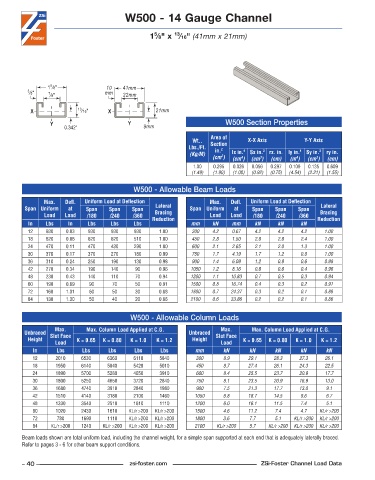
W500 - 14 Gauge Channel


                                                   5
                                                          13
                                                  1 ⁄8" x  ⁄16" (41mm x 21mm)


                 5
                 1 ⁄8"              10   41mm
          3 ⁄8"  7 ⁄8"             mm    22mm

           X              13 ⁄16"   X               21mm

                 Y                         Y                               W500 Section Properties
                      0.342"                    9mm
                                                                      Area of
                                                                Wt..   Section    X-X Axis          Y-Y Axis
                                                               Lbs./Ft.   in. 2
                                                               (Kg/M)        lx in. 4   Sx in. 3  rx. in. ly in. 4  Sy in. 3  ry in.
                                                                      (cm )  (cm )  (cm )  (cm)  (m )  (cm )  (cm)
                                                                         2
                                                                                4
                                                                                      3
                                                                                                        3
                                                                                                  4
                                                                1 .00  0 .295  0 .026  0 .056  0 .297  0 .109  0 .135  0 .609
                                                                (1.49)  (1.90)  (1.08)  (0.92)  (0.75)  (4.54)  (2.21)  (1.55)
                                             W500 - Allowable Beam Loads
               Max.    Defl.   Uniform Load at Deflection             Max.    Defl.   Uniform Load at Deflection
         Span Uniform   at   Span    Span   Span    Lateral    Span Uniform   at   Span    Span   Span    Lateral
               Load   Load   /180    /240   /360    Bracing           Load  Load    /180   /240    /360   Bracing
          In    Lbs    In     Lbs    Lbs     Lbs   Reduction   mm     kN     mm     kN      kN     kN    Reduction
          12    930    0 .03  930    930     930     1 .00      300   4.2    0.67   4.2     4.2    4.2     1.00
          18    620    0 .06  620    620     510     1 .00      450   2.8    1.50   2.8     2.8    2.4     1.00
          24    470    0 .11  470    430     290     1 .00      600   2.1    2.65   2.1     2.0    1.3     1.00
          30    370    0 .17  370    270     180     0 .99      750   1.7    4.19   1.7     1.2    0.8     1.00
          36    310    0 .24  250    190     130     0 .98      900   1.4    6.09   1.2     0.9    0.6     0.98
          42    270    0 .34  190    140     90      0 .96     1050   1.2    8.16   0.8     0.6    0.4     0.96
          48    230    0 .43  140    110     70      0 .94     1200   1.1   10.83   0.7     0.5    0.3     0.94
          60    190    0 .69  90      70     50      0 .91     1500   0.8   16.74   0.4     0.3    0.2     0.91
          72    160    1 .01  60      50     30      0 .88     1800   0.7   24.37   0.3     0.2    0.1     0.88
          84    130    1 .30  50      40     20      0 .86     2100   0.6   33.86   0.2     0.2    0.1     0.86


                                            W500 - Allowable Column Loads
                   Max.      Max. Column Load Applied at C.G.            Max.      Max. Column Load Applied at C.G.
         Unbraced  Slot Face                                   Unbraced  Slot Face
          Height          K = 0.65  K = 0.80  K = 1.0  K = 1.2  Height          K = 0.65  K = 0.80  K = 1.0  K = 1.2
                   Load                                                  Load
            In     Lbs      Lbs     Lbs      Lbs     Lbs         mm       kN      kN       kN      kN      kN
            12     2010     6530    6360     6110    5840        300      8.9     29.1    28.3     27.3    26.1
            18     1950     6140    5840     5420    5010        450      8.7     27.4    26.1     24.3    22.5
            24     1890     5700    5280     4650    3910        600      8.4     25.5    23.7     20.9    17.7
            30     1800     5250    4650     3720    2840        750      8.1     23.5    20.9     16.9    13.0
            36     1680     4740    3910     2840    1980        900      7.5     21.3    17.7     13.0    9.1
            42     1510     4140    3180     2100    1460        1050     6.8     18.7    14.5     9.6     6.7
            48     1330     3540    2510     1610    1110        1200     6.0     16.1    11.5     7.4     5.1
            60     1020     2430    1610   KL/r >200  KL/r >200  1500     4.6     11.2     7.4     4.7   KL/r >200
            72      780     1690    1110   KL/r >200  KL/r >200  1800     3.6     7.7      5.1   KL/r >200  KL/r >200
            84    KL/r >200  1240  KL/r >200  KL/r >200  KL/r >200  2100  KL/r >200  5.7  KL/r >200  KL/r >200  KL/r >200
        Beam loads shown are total uniform load, including the channel weight, for a simple span supported at each end that is adequately laterally braced.
        Refer to pages 3 - 6 for other beam support conditions.


        – 40 –                             zsi-foster.com                             ZSi-Foster Channel Load Data
   35   36   37   38   39   40   41   42   43   44   45