Page 36 - ZSi-Foster Channel Loads
P. 36

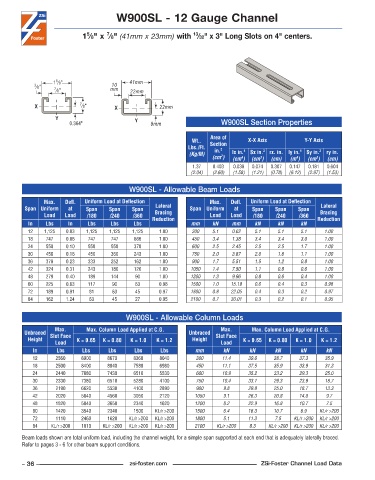
W900SL - 12 Gauge Channel


                                    7
                             5
                                                                13
                            1 ⁄8" x  ⁄8" (41mm x 23mm) with  ⁄32" x 3" Long Slots on 4" centers.


                   5
                  1 ⁄8"                    41mm
                                     10
            3 ⁄8"  7 ⁄8"             mm    22mm
            X              7 ⁄8"      X              22mm

                   Y                         Y
                        0.364"                    9mm                    W900SL Section Properties
                                                                      Area of
                                                                Wt..   Section    X-X Axis          Y-Y Axis
                                                              Lbs./Ft.   in. 2
                                                               (Kg/M)        lx in. 4   Sx in. 3  rx. in. ly in. 4  Sy in. 3  ry in.
                                                                         2
                                                                      (cm )  (cm )  (cm )  (cm)  (m )  (cm )  (cm)
                                                                                4
                                                                                      3
                                                                                                        3
                                                                                                  4
                                                                1 .37  0 .403  0 .038  0 .074  0 .307  0 .147  0 .181  0 .604
                                                               (2.04)  (2.60)  (1.58)  (1.21)  (0.78)  (6.12)  (2.97)  (1.53)
                                           W900SL - Allowable Beam Loads
               Max.    Defl.   Uniform Load at Deflection             Max.    Defl.   Uniform Load at Deflection
         Span Uniform   at   Span    Span   Span    Lateral    Span Uniform   at   Span    Span   Span    Lateral
               Load   Load   /180    /240   /360    Bracing           Load  Load    /180   /240    /360   Bracing
          In    Lbs    In     Lbs    Lbs     Lbs   Reduction   mm     kN     mm     kN      kN     kN    Reduction
          12   1,125   0 .03  1,125  1,125  1,125    1 .00      300   5.1    0.62   5.1     5.1    5.1     1.00
          18    747    0 .06  747    747     666     1 .00      450   3.4    1.38   3.4     3.4    3.0     1.00
          24    558    0 .10  558    558     378     1 .00      600   2.5    2.45   2.5     2.5    1.7     1.00
          30    450    0 .16  450    360     243     1 .00      750   2.0    3.87   2.0     1.6    1.1     1.00
          36    378    0 .23  333    252     162     1 .00      900   1.7    5.51   1.5     1.2    0.8     1.00
          42    324    0 .31  243    180     126     1 .00     1050   1.4    7.50   1.1     0.8    0.6     1.00
          48    279    0 .40  189    144     90      1 .00     1200   1.3    9.96   0.8     0.6    0.4     1.00
          60    225    0 .63  117     90     63      0 .98     1500   1.0   15.19   0.6     0.4    0.3     0.98
          72    189    0 .91  81      63     45      0 .97     1800   0.8   22.05   0.4     0.3    0.2     0.97
          84    162    1 .24  63      45     27      0 .95     2100   0.7   30.01   0.3     0.2    0.1     0.95


                                          W900SL - Allowable Column Loads
                   Max.      Max. Column Load Applied at C.G.            Max.      Max. Column Load Applied at C.G.
         Unbraced  Slot Face                                   Unbraced  Slot Face
          Height          K = 0.65  K = 0.80  K = 1.0  K = 1.2  Height          K = 0.65  K = 0.80  K = 1.0  K = 1.2
                   Load                                                  Load
            In     Lbs      Lbs     Lbs      Lbs     Lbs         mm       kN      kN       kN      kN      kN
            12     2560     8900    8670     8360    8040        300      11.4    39.6    38.7     37.3    35.9
            18     2500     8400    8040     7580    6980        450     11.1     37.5    35.9     33.9    31.3
            24     2440     7880    7430     6510    5530        600     10.9     35.2    33.2     29.3    25.0
            30     2330     7380    6510     5280    4100        750     10.4     33.1    29.3     23.9    18.7
            36     2190     6620    5530     4100    2890        900      9.8     29.8    25.0     18.7    13.3
            42     2020     5840    4560     3050    2120        1050     9.1     26.3    20.8     14.0    9.7
            48     1820     5040    3650     2340    1620        1200     8.2     22.9    16.8     10.7    7.5
            60     1420     3540    2340     1500   KL/r >200    1500     6.4     16.3    10.7     6.9   KL/r >200
            72     1110     2460    1620   KL/r >200  KL/r >200  1800     5.1     11.3     7.5   KL/r >200  KL/r >200
            84    KL/r >200  1810  KL/r >200  KL/r >200  KL/r >200  2100  KL/r >200  8.3  KL/r >200  KL/r >200  KL/r >200
        Beam loads shown are total uniform load, including the channel weight, for a simple span supported at each end that is adequately laterally braced.
        Refer to pages 3 - 6 for other beam support conditions.


        – 36 –                             zsi-foster.com                             ZSi-Foster Channel Load Data
   31   32   33   34   35   36   37   38   39   40   41