Page 44 - ZSi-Foster Channel Loads
P. 44

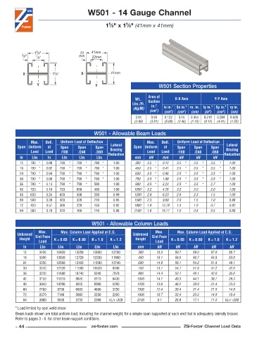
W501 - 14 Gauge Channel


                                                   5
                                                           5
                                                  1 ⁄8" x 1 ⁄8" (41mm x 41mm)


                  5
                 1 ⁄8"                10   41mm
           3 ⁄8"  7 ⁄8"               mm    22mm


                          5
            X            1 ⁄8"         X            41mm
                  Y                          Y                             W501 Section Properties

                                                                      Area of
                                                                Wt..   Section    X-X Axis          Y-Y Axis
                                                              Lbs./Ft.   in. 2
                                                               (Kg/M)        lx in. 4   Sx in. 3  rx. in. ly in. 4  Sy in. 3  ry in.
                                                                         2
                                                                      (cm )  (cm )  (cm )  (cm)  (m )  (cm )  (cm)
                                                                                      3
                                                                                                        3
                                                                                                  4
                                                                                4
                                                                2 .01  0 .59  0 .122  0 .15  0 .454  0 .219  0 .269  0 .609
                                                               (2.99)  (3.81)  (5.08)  (2.46)  (1.15)  (9.12)  (4.41)  (1.55)
                                             W501 - Allowable Beam Loads
               Max.    Defl.   Uniform Load at Deflection            Max.    Defl.   Uniform Load at Deflection
         Span Uniform   at   Span    Span    Span   Lateral    Span Uniform   at   Span    Span    Span   Lateral
               Load   Load   /180    /240    /360   Bracing          Load   Load   /180    /240    /360   Bracing
          In    Lbs    In     Lbs     Lbs     Lbs  Reduction   mm     kN    mm      kN      kN      kN   Reduction
          12   790 *  0 .00  790  *  790  *  790 *    1 .00     300  3.5 *  0.12   3.5  *  3.5  *  3.5  *  1.00
          18   790 *  0 .02  790  *  790  *  790 *    1 .00     450  3.5 *  0.41   3.5  *  3.5  *  3.5  *  1.00
          24   790 *  0 .04  790  *  790  *  790 *    1 .00     600  3.5 *  0.96   3.5  *  3.5  *  3.5  *  1.00
          30   790 *  0 .08  790  *  790  *  790 *    1 .00     750  3.5 *  1.88   3.5  *  3.5  *  3.5  *  1.00
          36   790 *  0 .13  790  *  790  *  590      1 .00     900  3.5 *  3.24   3.5  *  3.5  *  2.7     1.00
          42   720    0 .19  720     650     430      1 .00    1050  3.2    4.76   3.2     3.0     2.0     1.00
          48   630    0 .25  630     500     330      0 .99    1200  2.8    6.23   2.8     2.3     1.5     1.00
          60   500    0 .39  420     320     210      0 .95    1500  2.3    9.69   2.0     1.5     1.0     0.96
          72   420    0 .57  300     220     150      0 .92    1800  1.9    13.79  1.3     1.0     0.7     0.92
          84   360    0 .78  220     160     110      0 .88    2100  1.6    18.77  1.0     0.8     0.5     0.88


                                            W501 - Allowable Column Loads
                   Max.      Max. Column Load Applied at C.G.            Max.      Max. Column Load Applied at C.G.
         Unbraced  Slot Face                                   Unbraced  Slot Face
          Height          K = 0.65  K = 0.80  K = 1.0  K = 1.2  Height          K = 0.65  K = 0.80  K = 1.0  K = 1.2
                   Load                                                  Load
            In      Lbs     Lbs     Lbs      Lbs     Lbs         mm       kN       kN      kN      kN       kN
            12     3430    13420    13250   13000    12720       300      15.3    59.7    59.0     57.9    56.7
            18     3390    13030    12720   12300    11880       450      15.1    58.0    56.7     54.8    53.0
            24     3350    12580    12160   11590    10740       600      14.9    56.1    54.2     51.8    48.1
            30     3310    12120    11590   10520    9340        750      14.7    54.1    51.8     47.2    42.0
            36     3230    11680    10740    9340    7870        900      14.4    52.1    48.1     42.0    35.6
            42     3150    11010    9820     8110    6430        1050     14.1    49.3    44.1     36.7    29.3
            48     3040    10290    8850     6900    5080        1200     13.6    46.2    39.9     31.4    23.3
            60     2760     8730    6900     4680    3250        1500     12.4    39.4    31.4     21.5    14.9
            72     2370     7140    5080     3250    2260        1800     10.7    32.4    23.3     14.9    10.4
            84     2000     5630    3730     2390   KL/r >200    2100     9.1     25.8    17.1     11.0  KL/r >200
        * Load limited by spot weld shear
        Beam loads shown are total uniform load, including the channel weight, for a simple span supported at each end that is adequately laterally braced.
        Refer to pages 3 - 6  for other beam support conditions.
        – 44 –                             zsi-foster.com                             ZSi-Foster Channel Load Data
   39   40   41   42   43   44   45   46   47   48   49