Page 48 - ZSi-Foster Channel Loads
P. 48

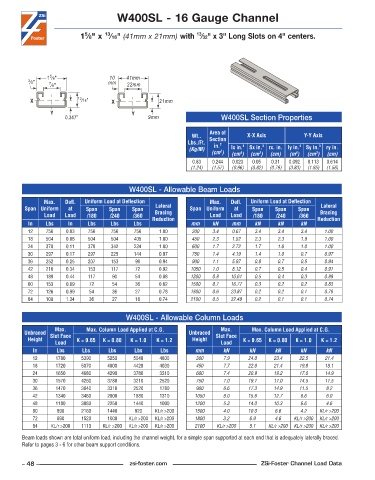
W400SL - 16 Gauge Channel


                                   13
                                                                 13
                             5
                           1 ⁄8" x  ⁄16" (41mm x 21mm) with  ⁄32" x 3" Long Slots on 4" centers.


                 5
                1 ⁄8"                10   41mm
          3 ⁄8"  7 ⁄8"              mm    22mm

           X              13 ⁄16"    X               21mm
                 Y                          Y
                      0.347"                     9mm                     W400SL Section Properties

                                                                     Area of
                                                                Wt..   Section    X-X Axis          Y-Y Axis
                                                              Lbs./Ft.   in. 2
                                                               (Kg/M)       lx in. 4   Sx in. 3  rx. in. ly in. 4  Sy in. 3  ry in.
                                                                      (cm )  (cm )  (cm )  (cm)  (m )  (cm )  (cm)
                                                                         2
                                                                                      3
                                                                                                  4
                                                                                                        3
                                                                               4
                                                                0 .83  0 .244  0 .023  0 .05  0 .31  0 .092  0 .113  0 .614
                                                               (1.24)  (1.57)  (0.96)  (0.82)  (0.79)  (3.83)  (1.85)  (1.56)
                                           W400SL - Allowable Beam Loads
               Max.    Defl.   Uniform Load at Deflection             Max.    Defl.   Uniform Load at Deflection
         Span Uniform   at   Span    Span   Span    Lateral    Span Uniform   at   Span    Span   Span    Lateral
               Load   Load   /180    /240   /360    Bracing           Load  Load    /180   /240    /360   Bracing
          In    Lbs    In     Lbs    Lbs     Lbs   Reduction   mm     kN     mm     kN      kN     kN    Reduction
          12    756    0 .03  756    756     756     1 .00      300   3.4    0.67   3.4     3.4    3.4     1.00
          18    504    0 .06  504    504     405     1 .00      450   2.3    1.52   2.3     2.3    1.9     1.00
          24    378    0 .11  378    342     234     1 .00      600   1.7    2.72   1.7     1.6    1.0     1.00
          30    297    0 .17  297    225     144     0 .97      750   1.4    4.19   1.4     1.0    0.7     0.97
          36    252    0 .25  207    153     99      0 .94      900   1.1    5.97   0.9     0.7    0.5     0.94
          42    216    0 .34  153    117     72      0 .92     1050   1.0    8.12   0.7     0.5    0.4     0.91
          48    189    0 .44  117     90     54      0 .88     1200   0.8   10.61   0.5     0.4    0.3     0.88
          60    153    0 .69  72      54     36      0 .82     1500   0.7   16.77   0.3     0.2    0.2     0.83
          72    126    0 .99  54      36     27      0 .78     1800   0.6   23.87   0.2     0.2    0.1     0.78
          84    108    1 .34  36      27     18      0 .74     2100   0.5   32.49   0.2     0.1    0.1     0.74


                                          W400SL - Allowable Column Loads
                   Max.      Max. Column Load Applied at C.G.            Max.      Max. Column Load Applied at C.G.
         Unbraced  Slot Face                                   Unbraced  Slot Face
          Height          K = 0.65  K = 0.80  K = 1.0  K = 1.2  Height          K = 0.65  K = 0.80  K = 1.0  K = 1.2
                   Load                                                  Load
            In     Lbs      Lbs     Lbs      Lbs     Lbs         mm       kN      kN       kN      kN      kN
            12     1780     5390    5250     5040    4800        300      7.9     24.0    23.4     22.5    21.4
            18     1720     5070    4800     4420    4030        450      7.7     22.6    21.4     19.8    18.1
            24     1650     4680    4290     3780    3310        600      7.4     20.9    19.2     17.0    14.9
            30     1570     4260    3780     3210    2520        750      7.0     19.1    17.0     14.5    11.5
            36     1470     3840    3310     2520    1780        900      6.6     17.3    14.9     11.5    8.2
            42     1340     3460    2800     1880    1310        1050     6.0     15.6    12.7     8.6     6.0
            48     1180     3080    2250     1440    1000        1200     5.3     14.0    10.3     6.6     4.6
            60      890     2180    1440     920    KL/r >200    1500     4.0     10.0     6.6     4.2   KL/r >200
            72      690     1520    1000   KL/r >200  KL/r >200  1800     3.2     6.9      4.6   KL/r >200  KL/r >200
            84    KL/r >200  1110  KL/r >200  KL/r >200  KL/r >200  2100  KL/r >200  5.1  KL/r >200  KL/r >200  KL/r >200
        Beam loads shown are total uniform load, including the channel weight, for a simple span supported at each end that is adequately laterally braced.
        Refer to pages 3 - 6 for other beam support conditions.


        – 48 –                             zsi-foster.com                             ZSi-Foster Channel Load Data
   43   44   45   46   47   48   49   50   51   52   53