Page 29 - ZSi-Foster Channel Loads
P. 29

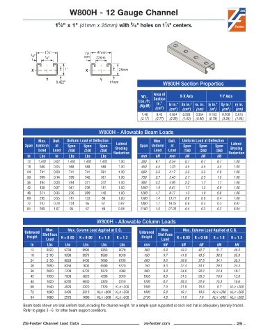
W800H - 12 Gauge Channel


                            5
                                                                              7
                                                              9
                           1 ⁄8" x 1" (41mm x 25mm) with  ⁄16" holes on 1 ⁄8" centers.


                       5
                      1 ⁄8"              10    41mm
                3 ⁄8"  7 ⁄8"             mm   22mm

                X              1"        X               25mm
                       Y                        Y
                           0.422"                   11mm                     W800H Section Properties


                                                                         Area of
                                                                   Wt..   Section    X-X Axis           Y-Y Axis
                                                                  Lbs./Ft.   in. 2
                                                                  (Kg/M)        lx in. 4   Sx in. 3  rx. in. ly in. 4  Sy in. 3  ry in.
                                                                             2
                                                                          (cm )  (cm )  (cm )  (cm)  (m )  (cm )  (cm)
                                                                                         3
                                                                                                            3
                                                                                                     4
                                                                                   4
                                                                    1 .46  0 .43  0 .054  0 .093  0 .354  0 .163  0 .200  0 .615
                                                                   (2.17)  (2.77)  (2.25)  (1.52)  (0.90)  (6.78)  (3.28)  (1.56)
                                               W800H - Allowable Beam Loads
                   Max.    Defl.   Uniform Load at Deflection            Max.    Defl.   Uniform Load at Deflection
             Span Uniform   at   Span   Span    Span   Lateral     Span Uniform   at   Span   Span    Span   Lateral
                   Load   Load   /180    /240   /360   Bracing           Load   Load   /180    /240   /360   Bracing
              In    Lbs    In    Lbs     Lbs    Lbs   Reduction    mm     kN    mm      kN     kN      kN   Reduction
              12   1,482  0 .02  1,482  1,482   1,482    1 .00     300    6.7   0.54    6.7    6.7     6.7     1.00
              18    988   0 .05  988     988    988      1 .00     450    4.5   1.23    4.5    4.5     4.5     1.00
              24    741   0 .09  741     741    561      1 .00     600    3.3   2.17    3.3    3.3     2.6     1.00
              30    599   0 .14  599     542    361      1 .00     750    2.7   3.43    2.7    2.5     1.6     1.00
              36    494   0 .20  494     371    247      1 .00     900    2.2   4.90    2.2    1.7     1.1     1.00
              42    428   0 .27  361     276    181      1 .00     1050   1.9   6.61    1.7    1.3     0.8     1.00
              48    371   0 .35  276     209    143      1 .00     1200   1.7   8.77    1.3    1.0     0.6     1.00
              60    295   0 .55  181     133     86      1 .00     1500   1.4   13.71   0.8    0.6     0.4     1.00
              72    247   0 .79  124     95      67      0 .97     1800   1.1   19.25   0.6    0.4     0.3     0.97
              84    209   1 .07   95     67      48      0 .94     2100   1.0   27.04   0.4    0.3     0.2     0.94


                                              W800H - Allowable Column Loads
                       Max.      Max. Column Load Applied at C.G.            Max.      Max. Column Load Applied at C.G.
             Unbraced  Slot Face                                  Unbraced  Slot Face
              Height          K = 0.65  K = 0.80  K = 1.0  K = 1.2  Height          K = 0.65  K = 0.80  K = 1.0  K = 1.2
                       Load                                                  Load
               In      Lbs      Lbs     Lbs      Lbs     Lbs        mm        kN      kN      kN       kN      kN
               12      2220    9730     9590    9350     9070        300      9.9     43.3    42.7    41.7     40.5
               18      2190    9390     9070    8580     8010        450      9.7     41.8    40.5    38.3     35.9
               24      2150    8920     8400    7600     6730        600      9.6     39.8    37.5    34.1     30.3
               30      2090    8350     7600    6500     5370        750      9.3     37.4    34.1    29.3     24.4
               36      2020    7700     6730    5370     4090        900      9.0     34.6    30.3    24.4     18.7
               42      1930    7000     5820    4290     3010       1050      8.6     31.5    26.3    19.6     13.8
               48      1820    6280     4930    3320     2310       1200      8.2     28.3    22.4    15.3     10.6
               60      1540    4820     3320    2120   KL/r >200    1500      7.0     21.9    15.3     9.7   KL/r >200
               72      1280    3490     2310   KL/r >200  KL/r >200  1800     5.8     16.1    10.6   KL/r >200  KL/r >200
               84      1060    2570     1690   KL/r >200  KL/r >200  2100     4.8     11.8    7.8    KL/r >200  KL/r >200
            Beam loads shown are total uniform load, including the channel weight, for a simple span supported at each end that is adequately laterally braced.
            Refer to pages 3 - 6  for other beam support conditions.


            ZSi-Foster Channel Load Data                            zsi-foster.com                             – 29 –
   24   25   26   27   28   29   30   31   32   33   34