Page 27 - ZSi-Foster Channel Loads
P. 27

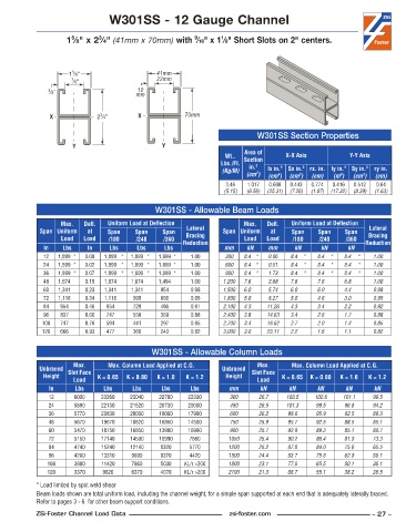
W301SS - 12 Gauge Channel


                      5
                              3
                                                                  1
                                                          9
                     1 ⁄8" x 2 ⁄4" (41mm x 70mm) with  ⁄16" x 1 ⁄8" Short Slots on 2" centers.

                      5
                     1 ⁄8"                     41mm
                      7 ⁄8"                    22mm
                                         10
               3 ⁄8"                     mm


                               3
                X             2 ⁄4"       X            70mm
                                                                             W301SS Section Properties
                      Y                          Y
                                                                         Area of
                                                                   Wt..   Section    X-X Axis           Y-Y Axis
                                                                  Lbs./Ft.   in. 2
                                                                  (Kg/M)        lx in. 4   Sx in. 3  rx. in.  ly in. 4  Sy in. 3  ry in.
                                                                            2
                                                                          (cm )  (cm )  (cm )  (cm)  (m )  (cm )  (cm)
                                                                                   4
                                                                                                     4
                                                                                                            3
                                                                                         3
                                                                   3 .46  1 .017  0 .608  0 .443  0 .774  0 .416  0 .512  0 .64
                                                                   (5.15)  (6.56)  (25.31)  (7.26)  (1.97)  (17.32)  (8.39)  (1.63)
                                               W301SS - Allowable Beam Loads
                   Max.    Defl.   Uniform Load at Deflection            Max.    Defl.   Uniform Load at Deflection
             Span Uniform   at   Span    Span    Span   Lateral    Span Uniform   at   Span    Span    Span   Lateral
                   Load   Load   /180    /240    /360   Bracing          Load   Load   /180    /240    /360  Bracing
              In   Lbs     In    Lbs     Lbs     Lbs   Reduction   mm     kN    mm      kN      kN     kN    Reduction
              12  1,899 *  0 .00  1,899 *  1,899 *  1,899 *  1 .00  300  8.4 *  0.06  8.4  *  8.4  *  8.4  *   1.00
              24  1,899 *  0 .02  1,899 *  1,899 *  1,899 *  1 .00  600  8.4 *  0.51  8.4  *  8.4  *  8.4  *   1.00
              36  1,899 *  0 .07  1,899 *  1,899 *  1,899 *  1 .00  900  8.4 *  1.73  8.4  *  8.4  *  8.4  *   1.00
              48  1,674    0 .15  1,674    1,674    1,494    1 .00  1,200  7.6    3.68  7.6     7.6     6.8     1.00
              60  1,341    0 .23  1,341    1,341    954    0 .98   1,500  6.0    5.74  6.0     6.0     4.4     0.98
              72  1,116    0 .34  1,116    999     666    0 .95    1,800  5.0    8.27  5.0     4.6     3.0     0.95
              84   954    0 .46  954     729     486     0 .91     2,100  4.3    11.26  4.3     3.4     2.2     0.92
              96   837    0 .60  747     558     369     0 .88     2,400  3.8    14.63  3.4     2.6     1.7     0.88
             108   747    0 .76  594     441     297     0 .85     2,700  3.4    18.62  2.7     2.0     1.4     0.85
             120   666    0 .93  477     360     243     0 .82     3,000  3.0    23.11  2.2     1.6     1.1     0.82


                                              W301SS - Allowable Column Loads
                       Max.      Max. Column Load Applied at C.G.            Max.      Max. Column Load Applied at C.G.
             Unbraced  Slot Face                                  Unbraced  Slot Face
              Height          K = 0.65  K = 0.80  K = 1.0  K = 1.2  Height          K = 0.65  K = 0.80  K = 1.0  K = 1.2
                       Load                                                  Load
               In      Lbs      Lbs     Lbs      Lbs     Lbs        mm        kN      kN      kN       kN      kN
               12      6000    23260   23040    22700   22330        300     26.7    103.5    102.6   101.1    99.5
               24      5890    22130   21520    20730   20000        450     26.5    101.3    99.5    96.8     94.2
               36      5770    20830   20000    19080   17990        600     26.2     98.6    95.9    92.5     89.3
               48      5670    19670   18820    16850   14500        750     25.9     95.7    92.5    88.5     85.1
               60      5470    18750   16850    13900   10990        900     25.7     92.9    89.3    85.1     80.7
               72      5150    17140   14500    10990    7860       1050     25.4     90.2    86.4    81.9     73.3
               84      4740    15240   12140    8320     5770       1200     25.2     87.8    84.0    75.8     65.5
               96      4280    13310    9890    6370     4420       1500     24.4     83.7    75.8    62.9     50.1
               108     3800    11420    7860    5030   KL/r >200    1800     23.1     77.0    65.5    50.1     36.1
               120     3370    9620     6370    4070   KL/r >200    2100     21.3     68.7    55.1    38.2     26.5
            * Load limited by spot weld shear
            Beam loads shown are total uniform load, including the channel weight, for a simple span supported at each end that is adequately laterally braced.
            Refer to pages 3 - 6  for other beam support conditions.
            ZSi-Foster Channel Load Data                            zsi-foster.com                             – 27 –
   22   23   24   25   26   27   28   29   30   31   32