Page 30 - ZSi-Foster Channel Loads
P. 30

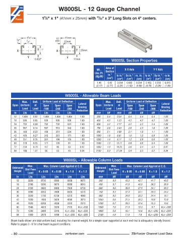
W800SL - 12 Gauge Channel


                                                                13
                              5
                            1 ⁄8" x 1" (41mm x 25mm) with  ⁄32" x 3" Long Slots on 4" centers.


                   5
                  1 ⁄8"              10    41mm
            3 ⁄8"  7 ⁄8"             mm   22mm


            X               1"        X              25mm
                   Y                        Y
                        0.422"                   11mm                    W800SL Section Properties


                                                                      Area of
                                                                Wt..   Section    X-X Axis          Y-Y Axis
                                                              Lbs./Ft.   in. 2
                                                               (Kg/M)        lx in. 4   Sx in. 3  rx. in. ly in. 4  Sy in. 3  ry in.
                                                                         2
                                                                      (cm )  (cm )  (cm )  (cm)  (m )  (cm )  (cm)
                                                                                4
                                                                                                        3
                                                                                                  4
                                                                                      3
                                                                1 .46  0 .43  0 .054  0 .093  0 .354  0 .163  0 .200  0 .615
                                                               (2.17)  (2.77)  (2.25)  (1.52)  (0.90)  (6.78)  (3.28)  (1.56)
                                           W800SL - Allowable Beam Loads
               Max.    Defl.   Uniform Load at Deflection             Max.    Defl.   Uniform Load at Deflection
         Span Uniform   at   Span    Span   Span    Lateral    Span Uniform   at   Span    Span   Span    Lateral
               Load   Load   /180    /240   /360    Bracing           Load  Load    /180   /240    /360   Bracing
          In    Lbs    In     Lbs    Lbs     Lbs   Reduction   mm     kN     mm     kN      kN     kN    Reduction
          12   1,404   0 .02  1,404  1,404  1,404    1 .00      300   6.4    0.54   6.4     6.4    6.4     1.00
          18    936    0 .05  936    936     936     1 .00      450   4.2    1.23   4.2     4.2    4.2     1.00
          24    702    0 .09  702    702     531     1 .00      600   3.2    2.17   3.2     3.2    2.4     1.00
          30    567    0 .14  567    513     342     1 .00      750   2.6    3.43   2.6     2.3    1.6     1.00
          36    468    0 .20  468    351     234     1 .00      900   2.1    4.90   2.1     1.6    1.1     1.00
          42    405    0 .27  342    261     171     1 .00     1050   1.8    6.61   1.6     1.2    0.8     1.00
          48    351    0 .35  261    198     135     1 .00     1200   1.6    8.77   1.2     0.9    0.6     1.00
          60    279    0 .55  171    126     81      1 .00     1500   1.3   13.71   0.8     0.6    0.4     1.00
          72    234    0 .79  117     90     63      0 .97     1800   1.0   19.25   0.6     0.4    0.3     0.97
          84    198    1 .07  90      63     45      0 .94     2100   0.9   27.04   0.4     0.3    0.2     0.94


                                          W800SL - Allowable Column Loads
                   Max.      Max. Column Load Applied at C.G.            Max.      Max. Column Load Applied at C.G.
         Unbraced  Slot Face                                   Unbraced  Slot Face
          Height          K = 0.65  K = 0.80  K = 1.0  K = 1.2  Height          K = 0.65  K = 0.80  K = 1.0  K = 1.2
                   Load                                                  Load
            In     Lbs      Lbs     Lbs      Lbs     Lbs         mm       kN      kN       kN      kN      kN
            12     2220     9730    9590     9350    9070        300      9.9     43.3    42.7     41.7    40.5
            18     2190     9390    9070     8580    8010        450      9.7     41.8    40.5     38.3    35.9
            24     2150     8920    8400     7600    6730        600      9.6     39.8    37.5     34.1    30.3
            30     2090     8350    7600     6500    5370        750      9.3     37.4    34.1     29.3    24.4
            36     2020     7700    6730     5370    4090        900      9.0     34.6    30.3     24.4    18.7
            42     1930     7000    5820     4290    3010        1050     8.6     31.5    26.3     19.6    13.8
            48     1820     6280    4930     3320    2310        1200     8.2     28.3    22.4     15.3    10.6
            60     1540     4820    3320     2120   KL/r >200    1500     7.0     21.9    15.3     9.7   KL/r >200
            72     1280     3490    2310   KL/r >200  KL/r >200  1800     5.8     16.1    10.6   KL/r >200  KL/r >200
            84     1060     2570    1690   KL/r >200  KL/r >200  2100     4.8     11.8     7.8   KL/r >200  KL/r >200
        Beam loads shown are total uniform load, including the channel weight, for a simple span supported at each end that is adequately laterally braced.
        Refer to pages 3 - 6 for other beam support conditions.


        – 30 –                             zsi-foster.com                             ZSi-Foster Channel Load Data
   25   26   27   28   29   30   31   32   33   34   35