Page 59 - ZSi-Foster Channel Loads
P. 59

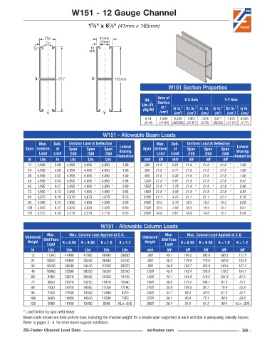
W151 - 12 Gauge Channel


                                           5
                                                   1
                                         1 ⁄8" x 6 ⁄2" (41mm x 165mm)
                      5
                     1 ⁄8"                     41mm
                      7 ⁄8"                    22mm
                3 ⁄8"                     mm
                                          10


                             1
                 X          6 ⁄2"          X          165mm
                                                                              W151 Section Properties

                                                                         Area of
                                                                   Wt..   Section     X-X Axis          Y-Y Axis
                                                                  Lbs./Ft.   in. 2   4     3           4     3
                                                                   (Kg/M)    2  lx in.  Sx in.  rx. in. ly in.  Sy in.  ry in.
                                                                                          3
                                                                                   4
                                                                                                     4
                                                                                                            3
                       Y                        Y                         (cm )  (cm )  (cm )  (cm)  (m )  (cm )  (cm)
                                                                    6 .14  1 .804  6 .339  1 .951  1 .874  0 .871  1 .072  0 .695
                                                                   (9.14)  (11.64) (263.85) (31.97)  (4.76)  (36.25) (17.57)  (1.77)
                                                W151 - Allowable Beam Loads
                   Max.    Defl.   Uniform Load at Deflection            Max.    Defl.   Uniform Load at Deflection
             Span Uniform   at   Span    Span    Span   Lateral    Span Uniform   at   Span    Span    Span   Lateral
                   Load   Load   /180    /240    /360   Bracing          Load   Load   /180    /240    /360  Bracing
              In   Lbs     In    Lbs     Lbs     Lbs   Reduction   mm     kN    mm      kN      kN     kN    Reduction
              12  4,890 *  0 .00  4,890 *  4,890 *  4,890 *  1 .00  300  21.8 *  0.01  21.8 *  21.8 *  21.8 *  1.00
              24  4,890 *  0 .00  4,890 *  4,890 *  4,890 *  1 .00  600  21.8 *  0.11  21.8 *  21.8 *  21.8 *  1.00
              36  4,890 *  0 .02  4,890 *  4,890 *  4,890 *  1 .00  900  21.8 *  0.38  21.8 *  21.8 *  21.8 *  1.00
              48  4,890 *  0 .04  4,890 *  4,890 *  4,890 *  0 .96  1200  21.8 *  0.91  21.8 *  21.8 *  21.8 *  0.97
              60  4,890 *  0 .07  4,890 *  4,890 *  4,890 *  0 .90  1500  21.8 *  1.78  21.8 *  21.8 *  21.8 *  0.90
              72  4,890 *  0 .13  4,890 *  4,890 *  4,890 *  0 .83  1800  21.8 *  3.08  21.8 *  21.8 *  21.8 *  0.83
              84  4,670    0 .19  4,670    4,670    4,670    0 .75  2100  21.1    4.75  21.1    21.1    21.1    0.76
              96  4,090    0 .25  4,090    4,090    4,090    0 .68  2400  18.5    6.19  18.5    18.5    18.5    0.69
             108  3,630    0 .32  3,630    3,630    3,420    0 .60  2700  16.4    7.84  16.4    16.4    15.7    0.61
             120  3,270    0 .39  3,270    3,270    2,770    0 .53  3000  14.8    9.67  14.8    14.8    12.7    0.54


                                               W151 - Allowable Column Loads
                       Max.      Max. Column Load Applied at C.G.            Max.      Max. Column Load Applied at C.G.
             Unbraced  Slot Face                                  Unbraced  Slot Face
              Height          K = 0.65  K = 0.80  K = 1.0  K = 1.2  Height          K = 0.65  K = 0.80  K = 1.0  K = 1.2
                       Load                                                  Load
               In      Lbs      Lbs     Lbs      Lbs     Lbs        mm        kN      kN      kN       kN      kN
               12     11040    41400   41060    40490   39830        300     49.1    184.2    182.8   180.3   177.5
               24     10820    39460   38240    36400   34410        600     48.2    175.9    170.6   162.6   153.9
               36     10490    36640   34410    31330   28370        900     46.8    163.7    153.9   140.4   127.4
               48     10080    33380   30320    26520   23250       1200     45.0    149.4    136.0   119.2   104.7
               60      9400    30070   26520    22520   19410       1500     42.1    134.9    119.2   101.4    87.5
               72      8650    26970   23250    19410   16540       1800     38.8    121.2    104.7   87.5     75.1
               84      7930    24210   20560    17050   12160       2100     35.6    109.0    92.7    76.9     55.8
               96      7280    21830   18390    13400    9310       2400     32.7     98.4    82.9    61.5     42.7
               108     6660    19820   16540    10590    7350       2700     30.1     89.4    75.1    48.6     33.8
               120     5800    18150   13400    8580   KL/r >200    3000     26.4     81.8    61.5    39.4   KL/r >200
            * Load limited by spot weld shear
            Beam loads shown are total uniform load, including the channel weight, for a simple span supported at each end that is adequately laterally braced.
            Refer to pages 3 - 6  for other beam support conditions.
            ZSi-Foster Channel Load Data                            zsi-foster.com                             – 59 –
   54   55   56   57   58   59   60   61   62   63   64