Page 54 - ZSi-Foster Channel Loads
P. 54

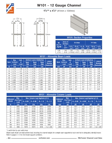
W101 - 12 Gauge Channel


                                                           7
                                                  5
                                                 1 ⁄8"" x 4 ⁄8" (41mm x 124mm)


                    5
                   1 ⁄8"                   41mm
                   7 ⁄8"                   22mm
             3 ⁄8"                    10
                                      mm


                          7
              X          4 ⁄8"         X           124mm
                                                                          W101: Section Properties

                                                                      Area of
                                                                Wt.   Section     X-X Axis          Y-Y Axis
                                                               Lbs./Ft.   2
                   Y                         Y                 (Kg/M)  in.   lx in. 4   Sx in. 3  rx. in. ly in. 4  Sy in. 3  ry in.
                                                                         2
                                                                       (cm )  (cm )  (cm )  (cm)  (m )  (cm )  (cm)
                                                                                4
                                                                                                        3
                                                                                                  4
                                                                                      3
                                                                4 .98  1 .463  2 .867  1 .176  1 .400  0 .674  0 .829  0 .679
                                                                (7.41)  (9.44)  (119.33) (19.27)  (3.56)  (28.05) (13.58)  (1.72)
                                             W101 - Allowable Beam Loads
               Max.    Defl.   Uniform Load at Deflection            Max.    Defl.   Uniform Load at Deflection
         Span Uniform   at   Span    Span    Span   Lateral    Span Uniform   at   Span    Span    Span   Lateral
               Load   Load   /180    /240    /360   Bracing          Load   Load   /180    /240    /360   Bracing
          In    Lbs    In     Lbs     Lbs     Lbs  Reduction   mm     kN    mm      kN      kN      kN   Reduction
          12   3,710 *  0 .00  3,710 *  3,710 *  3,710 *  1 .00  300  16.5 *  0.02  16.5 *  16.5 *  16.5 *  1.00
          24   3,710 *  0 .01  3,710 *  3,710 *  3,710 *  1 .00  600  16.5 *  0.19  16.5 *  16.5 *  16.5 *  1.00
          36   3,710 *  0 .03  3,710 *  3,710 *  3,710 *  1 .00  900  16.5 *  0.65  16.5 *  16.5 *  16.5 *  1.00
          48   3,710 *  0 .06  3,710 *  3,710 *  3,710 *  0 .98  1200  16.5 *  1.53  16.5 *  16.5 *  16.5 *  0.98
          60   3,710 *  0 .12  3,710 *  3,710 *  3,710 *  0 .92  1500  16.5 *  2.99  16.5 *  16.5 *  16.5 *  0.93
          72   3,290    0 .19  3,290    3,290    3,290    0 .87  1800  14.9    4.65  14.9    14.9    14.9    0.87
          84   2,820    0 .26  2,820    2,820    2,560    0 .81  2100  12.7    6.32  12.7    12.7    11.7    0.82
          96   2,470    0 .34  2,470    2,470    1,960    0 .75  2400  11.1    8.25  11.1    11.1    9.0     0.76
          108  2,190    0 .42  2,190    2,190    1,550    0 .69  2700  9.9    10.47  9.9     9.9     7.1     0.70
          120  1,970    0 .52  1,970    1,880    1,250    0 .64  3000  8.9    12.89  8.9     8.6     5.7     0.65


                                            W101 - Allowable Column Loads
                   Max.      Max. Column Load Applied at C.G.            Max.      Max. Column Load Applied at C.G.
         Unbraced  Slot Face                                   Unbraced  Slot Face
          Height          K = 0.65  K = 0.80  K = 1.0  K = 1.2  Height          K = 0.65  K = 0.80  K = 1.0  K = 1.2
                   Load                                                  Load
            In      Lbs     Lbs     Lbs      Lbs     Lbs         mm       kN       kN      kN      kN       kN
            12     8890    33570    33290   32840    32320       300      39.6    149.4   148.2   146.3    144.0
            24     8730    32030    31100   29720    28280       600      38.9    142.7   138.7   132.7    126.4
            36     8490    29900    28280   26150    24190       900      37.8    133.4   126.4   117.0    108.4
            48     8220    27560    25470   23020    21020       1200     36.7    123.2   114.1   103.2    94.3
            60     7840    25310    23020   20590    17300       1500     35.0    113.3   103.2    92.3    78.6
            72     7370    23300    21020   17300    12800       1800     33.0    104.4   94.3     78.6    58.8
            84     6870    21600    18880   13530    9410        2100     30.9    96.8    85.6     62.0    43.2
            96     6210    20180    15750   10370    7200        2400     28.0    90.5    71.8     47.6    33.1
           108     5510    17890    12800    8190    5690        2700     25.0    81.2    58.8     37.6    26.1
           120     4850    15370    10370    6640   KL/r >200    3000     22.0    70.1    47.6     30.5  KL/r >200
        * Load limited by spot weld shear
        Beam loads shown are total uniform load, including the channel weight, for a simple span supported at each end that is adequately laterally braced.
        Refer to pages 3 - 6  for other beam support conditions.
        – 54 –                             zsi-foster.com                             ZSi-Foster Channel Load Data
   49   50   51   52   53   54   55   56   57   58   59