Page 62 - ZSi-Foster Channel Loads
P. 62

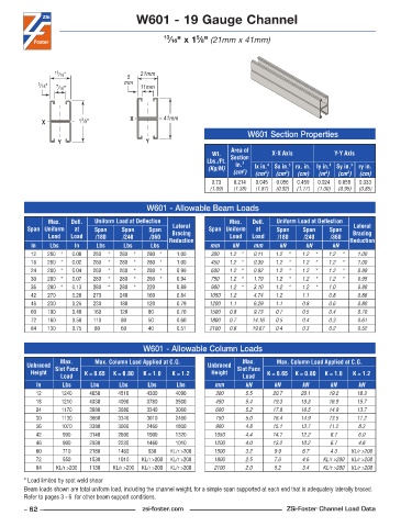
W601 - 19 Gauge Channel


                                                           5
                                                  13 ⁄16" x 1 ⁄8" (21mm x 41mm)


                 13 ⁄16"               5   21mm
            3 ⁄16"  7 ⁄16"            mm   11mm


                         5
             X          1 ⁄8"           X         41mm
                                                                           W601 Section Properties
                  Y                         Y
                                                                      Area of
                                                                Wt.   Section     X-X Axis          Y-Y Axis
                                                              Lbs./Ft.   in. 2
                                                               (Kg/M)        lx in. 4   Sx in. 3  rx. in. ly in. 4  Sy in. 3  ry in.
                                                                      (cm )  (cm )  (cm )  (cm)  (m )  (cm )  (cm)
                                                                         2
                                                                                      3
                                                                                4
                                                                                                  4
                                                                                                        3
                                                                0 .73  0 .214  0 .045  0 .056  0 .459  0 .024  0 .058  0 .333
                                                               (1.09)  (1.38)  (1.87)  (0.92)  (1.17)  (1.00)  (0.95)  (0.85)
                                             W601 - Allowable Beam Loads
               Max.    Defl.   Uniform Load at Deflection            Max.    Defl.   Uniform Load at Deflection
         Span Uniform   at   Span    Span    Span   Lateral    Span Uniform   at   Span    Span    Span   Lateral
               Load   Load   /180    /240    /360   Bracing          Load   Load   /180    /240    /360   Bracing
          In    Lbs    In     Lbs     Lbs     Lbs  Reduction   mm     kN    mm      kN      kN      kN   Reduction
          12   280 *  0 .00  280  *  280  *  280 *    1 .00     300  1.2 *  0.11   1.2  *  1.2  *  1.2  *  1.00
          18   280 *  0 .02  280  *  280  *  280 *    1 .00     450  1.2 *  0.39   1.2  *  1.2  *  1.2  *  1.00
          24   280 *  0 .04  280  *  280  *  280 *    0 .99     600  1.2 *  0.92   1.2  *  1.2  *  1.2  *  0.99
          30   280 *  0 .07  280  *  280  *  280 *    0 .94     750  1.2 *  1.79   1.2  *  1.2  *  1.2  *  0.95
          36   280 *  0 .13  280  *  280  *  220      0 .89     900  1.2 *  3.10   1.2  *  1.2  *  1.0     0.90
          42   270    0 .20  270     240     160      0 .84    1050  1.2    4.74   1.2     1.1     0.8     0.86
          48   230    0 .25  230     180     120      0 .79    1200  1.1    6.29   1.1     0.8     0.6     0.80
          60   190    0 .40  160     120     80       0 .70    1500  0.8    9.73   0.7     0.5     0.4     0.70
          72   160    0 .58  110     80      50       0 .60    1800  0.7    14.16  0.5     0.4     0.3     0.61
          84   130    0 .75  80      60      40       0 .51    2100  0.6    19.67  0.4     0.3     0.2     0.52


                                            W601 - Allowable Column Loads
                   Max.      Max. Column Load Applied at C.G.            Max.      Max. Column Load Applied at C.G.
         Unbraced  Slot Face                                   Unbraced  Slot Face
          Height          K = 0.65  K = 0.80  K = 1.0  K = 1.2  Height          K = 0.65  K = 0.80  K = 1.0  K = 1.2
                   Load                                                  Load
            In      Lbs     Lbs     Lbs      Lbs     Lbs         mm       kN       kN      kN      kN       kN
            12     1240     4650    4510     4300    4090        300      5.5     20.7    20.1     19.2    18.3
            18     1210     4330    4090     3780    3500        450      5.4     19.3    18.3     16.9    15.7
            24     1170     3980    3680     3340    3060        600      5.2     17.8    16.5     14.9    13.7
            30     1130     3660    3340     3010    2460        750      5.0     16.4    14.9     13.5    11.2
            36     1070     3380    3060     2460    1800        900      4.8     15.1    13.7     11.2    8.3
            42      990     3140    2690     1900    1320        1050     4.4     14.1    12.2     8.7     6.0
            48      900     2930    2230     1460    1010        1200     4.0     13.2    10.2     6.7     4.6
            60      710     2180    1460     930    KL/r >200    1500     3.2     9.9      6.7     4.3   KL/r >200
            72      550     1530    1010   KL/r >200  KL/r >200  1800     2.5     7.0      4.6   KL/r >200  KL/r >200
            84    KL/r >200  1130  KL/r >200  KL/r >200  KL/r >200  2100  2.0     5.2      3.4   KL/r >200  KL/r >200
        * Load limited by spot weld shear
        Beam loads shown are total uniform load, including the channel weight, for a simple span supported at each end that is adequately laterally braced.
        Refer to pages 3 - 6  for other beam support conditions.
        – 62 –                             zsi-foster.com                             ZSi-Foster Channel Load Data
   57   58   59   60   61   62   63   64   65   66